SCR Elektroniks Pvt Ltd
JAGUAR HEAT PUMP UNIT
(IS 4250 / IS 302)
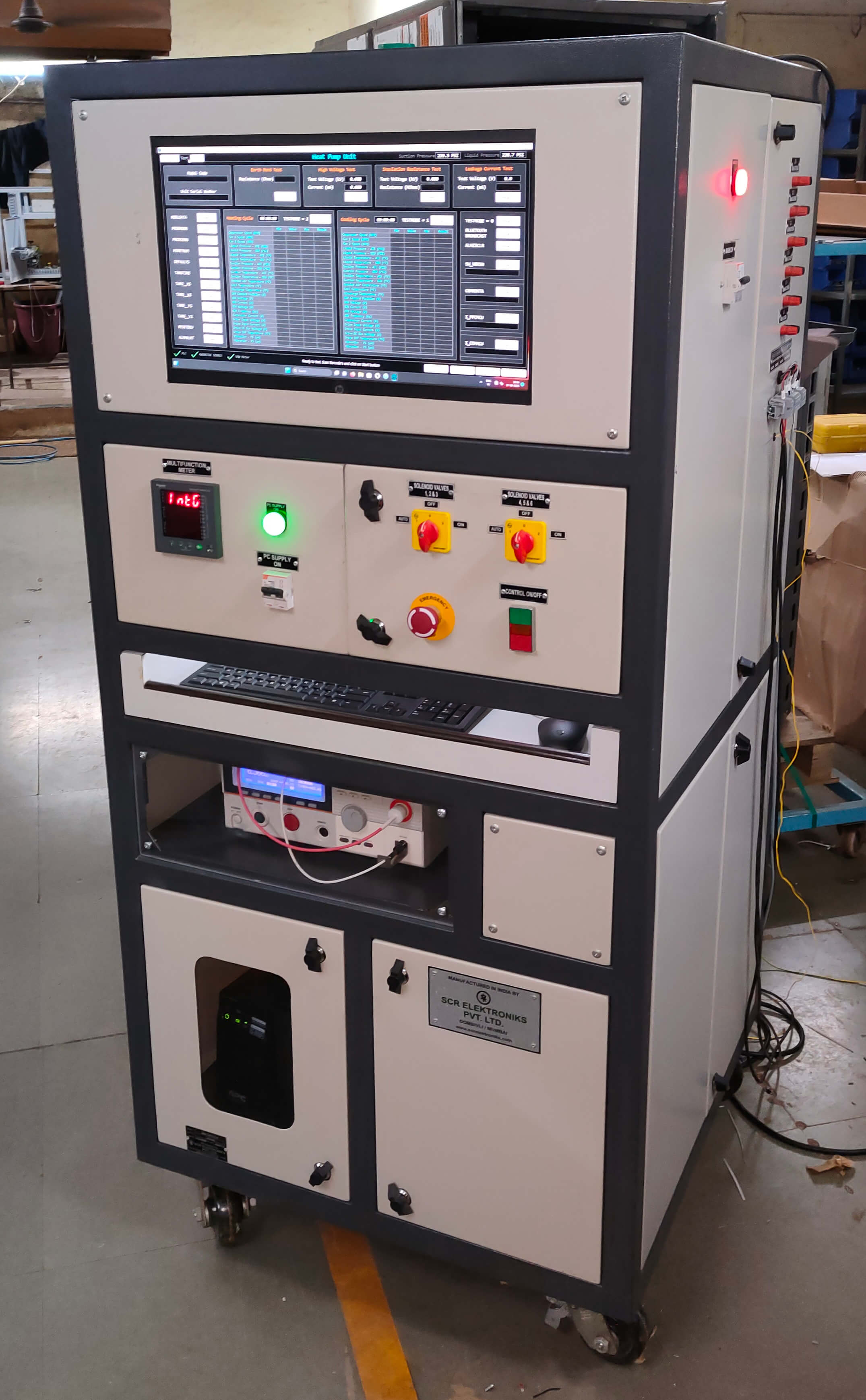 The Test Bench will have only PC modes of operation. All the tests will be carried out sequentially and the Data will be displayed and stored on PC. Lab VIEW based software and Siemens make PLC as an Interface module will be used to control the whole sequence. Option will be given for selection of test. If in different models of AC Tests are different, then that can be done by selecting the type no. (model) of AC
Earth Bond Test
In this test 10Amp AC current will be passed through Earth Path and the resistance of that Path will be measured and displayed on PC Screen. If the resistance is more than the set value (0.1 Ohms). Fail indication will be given & test will be terminated
Solid state source will be used for HV Test and Insulation Test
High Voltage Test with Ramp up / Down facility
In this test 0 to 6kV AC/DC Solid State source will be provided. High voltage (1.5kV) will be connected between live parts and will have metal body of the AC. If the leakage current will be more than the set value Fail Indication will be given & test will be terminated. Facility to set trip current from 1mA to 40mA for AC & 1mA to 10mA through PC
Insulation Test (Megger Test)
In this test 500V DC will be applied across the live parts in OFF condition and metal body of AC and the insulation resistance is measured and displayed on PC Screen. If the resistance is less than the set value 'Fail' indications will be given and test will be terminated
Earth Leakage Current Test
This test will be carried out with Run (Performance) Test. Rated Supply will be given to the AC and Leakage Current of Earth Path is measured and displayed on the PC Screen. If the current is more than the set value. Fail Indication will be given & Test will be terminated. Facility to set current limit 1mA to 15mA on PC. Leakage Current will be added for each device for comparing the limit
Performance (Run Test)
In this test rated voltage will be applied to the AC and current, wattage will be displayed on PC. Testing will be followed by 19/22C, 19/22d, 19/22e, 19/22f, 19/22j, 19/22j points
• RPM of Fan Motor will be indicated by using optical sensor (Optional)
• There will be two pressure Transducer to indicate low pressure and High pressure of the compressor
• Test time of each test will be settable and any test can be skipped if not required. In Auto mode all the tests will be carried out sequentially and if failure is detected next all the tests will be terminated giving Test over signal
• The separate output will be provided for five valves V1, V2, V3, V4, V5 of charge unit
• MS Fabricated panel Trolley Type duly powder coated
• Input Supply : 3 Phase 4 Wire 415V AC 50 Hz 6 max. For Unit under test supply will be given through your solid state source 240V/35A Single Phase
- Digital indicating meters with class 1 accuracy
- Indicating Lap for OK,NOT OK ,TEST ON indications.
- The test will be selected with push button & contactors and there will not be necessity to change the connections.
- Input Supply : 230V AC , 10A with MCB protection
- Variable Voltage Source to give 0 - 300 V / 4 Amps AC.
- Digital Wattmeter 0 - 1 KW.
- Digital Voltmeter 0 - 300 Volt.
- Digital Ammeter 0 - 4 Amps.
- Facility to carryout Leakage Current Test at 240 V. The current will be indicated on Digital Ammeter. If the current exceeds 210 Micro Amps. "NOT OK” lamp will glow. If the Timers are provided for test time and for changing the polarity of output supply.
- HV tester 0 - 1.5 KV / 5 mA with timer to set time 0 - 10 sec. Digital Voltmeter will read the out put HV Voltage. At the end of time the indication of "OK" & "NOT OK" will be given on lamps.
- Digital RPM Indication 5 digit.
- Tripping current selection: 2mA , 5mA ,10mA , 25 mA ,50 mA.
The tester can be customized with respect to number of stations, range of the current (wattage), voltage, and also the maximum value of high voltage. The tester can also be customized w r t PLC / PC based or microcontroller based semi automatic version
The tester conducts high voltage test on the mixer and also electrical performance test. Expected current is pre-programmed in the test system and if the current exceeds the range, the tst bench declares overload / no load depending upon the test outcome